Fabricators: Difference between revisions
No edit summary |
|||
| (41 intermediate revisions by 2 users not shown) | |||
| Line 1: | Line 1: | ||
= | __NOTOC__ | ||
<!-- ===================== HERO BANNER ===================== --> | |||
<div style="margin:0 0 20px 0; padding:18px 22px; border:1px solid rgba(128,128,128,0.35); border-left:5px solid #3366cc; border-radius:6px; background:rgba(51,102,204,0.06);"> | |||
<div style="font-size:170%; font-weight:bold; margin-bottom:4px;">automet® for Fabricators</div> | |||
<div style="margin-bottom:8px;">Three core steps: Design Input, Field/Shop Survey, and Analysis. Follow this workflow in order to inspect, verify, and correct pipe spools during fabrication.</div> | |||
<div style="font-size:90%;">[[Main Page|← Return to Main Page]]</div> | |||
</div> | |||
= | <!-- ===================== PROCESS AT A GLANCE ===================== --> | ||
<div style="display:flex; flex-wrap:wrap; gap:14px; margin:0 0 20px 0;"> | |||
<div style="flex:1 1 200px; padding:14px 18px; border:1px solid rgba(128,128,128,0.35); border-top:4px solid #00af89; border-radius:6px; background:#fafafa;"> | |||
'''1 · [[#Step 1: Design Input|Design Input]]'''<br>Import or manually construct the baseline spool model (.DES). | |||
</div> | |||
<div style="flex:1 1 200px; padding:14px 18px; border:1px solid rgba(128,128,128,0.35); border-top:4px solid #e67e22; border-radius:6px; background:#fafafa;"> | |||
'''2 · [[#Step 2: Survey Execution|Survey Execution]]'''<br>Observe physical flanges, supports, and pipe ends against the design. | |||
</div> | |||
<div style="flex:1 1 200px; padding:14px 18px; border:1px solid rgba(128,128,128,0.35); border-top:4px solid #9b59b6; border-radius:6px; background:#fafafa;"> | |||
'''3 · [[#Step 3: Analysis and Deviation Verification|Analysis & Report]]'''<br>Evaluate vector deviations, alignment touch points, and export reports. | |||
</div> | |||
</div> | |||
= | <!-- ===================== PRE-FLIGHT SETUP ===================== --> | ||
<div style="padding:14px 18px; margin:0 0 24px 0; border:1px solid rgba(128,128,128,0.35); border-left:5px solid #3366cc; border-radius:6px; background:rgba(51,102,204,0.04);"> | |||
<div style="font-weight:bold; font-size:105%; margin-bottom:4px;">Before starting the survey:</div> | |||
Power on the Total Station and establish a connection to your laptop via Bluetooth or Leica GEV267 serial cable. | |||
<br><br> | |||
<b>Video guide:</b> [https://www.youtube.com/watch?v=ajIbQ0lo2gY Getting Started & Hardware Setup] | |||
</div> | |||
== | == Step 1: Design Input == | ||
automet® FAB '''requires a baseline design file (`.DES`)''' to compare measured survey points against drawing specifications. | |||
<div style="display:flex; flex-wrap:wrap; gap:16px; margin:14px 0 20px 0;"> | |||
<div style="flex:1 1 320px; padding:16px 20px; border:1px solid rgba(128,128,128,0.35); border-top:4px solid #00af89; border-radius:6px; background:#ffffff;"> | |||
<div style="font-size:115%; font-weight:bold; margin-bottom:8px; color:#007a60;">Method 1 · Import IDF or PCF File</div> | |||
The fastest method. Import an exported plant design file (IDF or PCF) directly into automet® FAB. The system automatically populates component specifications, flange ratings, and segment lengths into a `.DES` file. | |||
<br> | |||
<b>Video guide:</b> [https://www.youtube.com/watch?v=mThSe3I5A5o Import IDF/PCF Files into automet®] | |||
</div> | |||
== | <div style="flex:1 1 320px; padding:16px 20px; border:1px solid rgba(128,128,128,0.35); border-top:4px solid #00af89; border-radius:6px; background:#ffffff;"> | ||
<div style="font-size:115%; font-weight:bold; margin-bottom:8px; color:#007a60;">Method 2 · Manual Design Entry</div> | |||
Build or edit the model manually using the Design Input module. Mastering manual entry is essential for updating client isometric drawings, editing gasket allowances, and modifying component lengths in the field. | |||
= | <br> | ||
<b>Video guide:</b> [https://www.youtube.com/watch?v=_oud6TeDFw0&list=PLfbSUslPQTHGocyxyWQTL0576i1GrYIyP&index=1 Manual Design Entry Video Playlist] | |||
</div> | |||
</div> | |||
== | == Step 2: Survey Execution == | ||
Once a design model (`.DES`) is loaded, you are ready to execute the survey. | |||
Survey | === Starting a survey session === | ||
Select the '''Run Survey''' button on the main menu. | |||
== | <gallery mode="packed" heights="250px"> | ||
File:Survey Main Menu - Run Survey.png|automet® main menu: Select Run Survey | |||
</gallery> | |||
<div style="display:flex; flex-wrap:wrap; gap:16px; margin:16px 0 20px 0;"> | |||
<div style="flex:1 1 320px; padding:16px 20px; border:1px solid rgba(128,128,128,0.35); border-top:4px solid #e67e22; border-radius:6px; background:#ffffff;"> | |||
<div style="font-size:115%; font-weight:bold; margin-bottom:8px; color:#c0392b;">Start New Survey</div> | |||
Select '''START NEW''' to generate a new survey file using the design name, automatically assigning the survey stage and revision number. | |||
== | <gallery mode="packed" heights="200px"> | ||
File:KB 117.png|Start New survey setup dialog | |||
</gallery> | |||
</div> | |||
<div style="flex:1 1 320px; padding:16px 20px; border:1px solid rgba(128,128,128,0.35); border-top:4px solid #e67e22; border-radius:6px; background:#ffffff;"> | |||
<div style="font-size:115%; font-weight:bold; margin-bottom:8px; color:#c0392b;">Continue Existing Survey</div> | |||
Select '''CONTINUE EXISTING''' to reload previous observations. This function requires that neither the spool nor total station has moved, or that control points are available for resection. | |||
== | <gallery mode="packed" heights="200px"> | ||
File:KB 118.png|Continue Existing survey dialog | |||
</gallery> | |||
</div> | |||
</div> | |||
=== Load design file and survey stage === | |||
1. Select the target design file using the file browser button (`...`). | |||
2. Choose the appropriate survey stage: | |||
#* '''In-Situ:''' Field measurements on installed piping networks prior to replacement. | |||
#* '''Tack Weld:''' Fabrication shop survey during pre-weld assembly. | |||
#* '''Post Weld:''' Final quality verification following full weld completion. | |||
== | <gallery mode="packed" heights="75px"> | ||
File:design file select.png|Design file selection dialog | |||
File:survey stage postweld.png|Selecting survey stage (Post Weld) | |||
</gallery> | |||
=== Pre-survey preparation checklist === | |||
Before selecting '''Start Capture''': | |||
1. '''Verify isometric geometry:''' Click the '''Isometric''' button to confirm the active model matches the physical spool. Flange numbers on the drawing must correspond directly to survey sequence order. | |||
2. '''Physical flange marking:''' Mark corresponding flange numbers directly onto physical flanges using paint markers. | |||
3. '''Targeting telescope start point:''' Aim the telescope at a accessible starting point on Flange 01. Hold the right mouse button to guide the motor laser. If target lock is lost, return the prism to the starting point to recover lock. | |||
4. '''Plan measurement path:''' Select an initial diameter point and proceed sequentially around the flange face in one continuous direction. | |||
<gallery mode="packed" heights="500px"> | |||
File:Iso of Spool 6.png|Isometric spool review window | |||
</gallery> | |||
< | |||
File: | |||
</ | |||
<div style="margin:16px 0; padding:14px 18px; border:1px solid rgba(128,128,128,0.3); border-left:4px solid #e67e22; border-radius:4px; background:rgba(230,126,34,0.04);"> | |||
<div style="font-weight:bold; font-size:105%; margin-bottom:4px; color:#333;">Moving survey start points</div> | |||
<b>Video guide:</b> [https://youtu.be/mVikoFuiKu8 Moving the Start Point During a Survey] (0:55) | |||
<br><br> | |||
<i>Summary:</i> Useful technique when surveying large spools with restricted line-of-sight. | |||
</div> | |||
=== Orientation Point (OP) for straight spools === | |||
An '''Orientation Point (OP)''' establishes Top Dead Centre (TDC) for straight pipe spools lacking distinguishing geometric features. | |||
1. Record a single point at the top center of Flange 01, positioned at Top Dead Centre between the upper bolt holes. | |||
2. Proceed with the flange survey as normal. | |||
3. Mark the physical OP location on the spool body to ensure correct site installation orientation. | |||
< | <div style="margin:16px 0; padding:14px 18px; border:1px solid rgba(128,128,128,0.3); border-left:4px solid #e67e22; border-radius:4px; background:rgba(230,126,34,0.04);"> | ||
<div style="font-weight:bold; font-size:105%; margin-bottom:4px; color:#333;">Orientation Point workflow</div> | |||
<b>Video guide:</b> [https://youtu.be/BmtSAx5Joms Orientation Point Procedure for Straight Spools] (2:56) | |||
</div> | |||
</ | |||
== | === Flange and support observations === | ||
<div style="margin:16px 0; padding:14px 18px; border:1px solid rgba(128,128,128,0.3); border-left:4px solid #e67e22; border-radius:4px; background:rgba(230,126,34,0.04);"> | |||
<b>Video guides:</b> | |||
* [https://www.youtube.com/watch?v=-EP23_tt0WI Spool Flange Survey Procedure] (3:28) | |||
* [https://youtu.be/bL57blkcubM Surveying Structural Supports and Base Plates] (2:23) | |||
</div> | |||
== | == Step 3: Analysis and Deviation Verification == | ||
The analysis module compares captured survey coordinates against design geometry to calculate dimensional deviations. | |||
<div style="padding:16px 20px; margin:16px 0 20px 0; border:1px solid rgba(128,128,128,0.35); border-top:4px solid #9b59b6; border-radius:6px; background:#ffffff;"> | |||
<div style="font-size:115%; font-weight:bold; margin-bottom:8px; color:#8e44ad;">Key Analytical Definitions</div> | |||
* '''Vector error:''' Coordinate distance (X, Y, Z) between measured work points and design centerlines. | |||
* '''Alignment error (Touch Point):''' High-point location on a flange face that will make contact first with a mating flange. The displayed value represents the gap opening (in mm) on the opposite side of the face. | |||
* '''Rotational error:''' Angular rotation error of bolt-hole patterns relative to design reference axes. | |||
</div> | |||
=== Interpreting deviation reports === | |||
<!-- ===================== 2 x 2 GRID ===================== --> | |||
<div style="display:flex; flex-wrap:wrap; gap:16px; margin:16px 0 20px 0;"> | |||
A | <!-- ROW 1 --> | ||
<div style="flex:1 1 45%; min-width:300px; padding:16px 20px; border:1px solid rgba(128,128,128,0.35); border-top:4px solid #9b59b6; border-radius:6px; background:#ffffff; text-align:center;"> | |||
<div style="font-weight:bold; margin-bottom:8px; color:#8e44ad;">Positional Vector Errors</div> | |||
<div style="margin-bottom:10px; text-align:left;">Vector arrows indicate the magnitude and direction of displacement. | |||
<br><br> | |||
<i>Example:</i> A flange reading +1.4 mm Z, +0.6 mm Y (North), and +0.8 mm X (East) requires physical adjustment in the opposite direction (-1.4 mm Z, -0.6 mm South, -0.8 mm West) to achieve zero deviation.</div> | |||
[[File:PDF Link VEGR 01.png|center|300px]] | |||
</div> | |||
< | <div style="flex:1 1 45%; min-width:300px; padding:16px 20px; border:1px solid rgba(128,128,128,0.35); border-top:4px solid #9b59b6; border-radius:6px; background:#ffffff; text-align:center;"> | ||
<div style="font-weight:bold; margin-bottom:8px; color:#8e44ad;">Bolt-Hole Rotational Error</div> | |||
<div style="margin-bottom:10px; text-align:left;">The blue curved arrow indicates rotational displacement (in mm or degrees) and direction of bolt-hole misalignment.</div> | |||
[[File:PDF Link VEGR 03.png|center|300px]] | |||
</ | </div> | ||
<!-- ROW 2 --> | |||
<div style="flex:1 1 45%; min-width:300px; padding:16px 20px; border:1px solid rgba(128,128,128,0.35); border-top:4px solid #9b59b6; border-radius:6px; background:#ffffff; text-align:center;"> | |||
<div style="font-weight:bold; margin-bottom:8px; color:#8e44ad;">Flange Touch Point (High Point)</div> | |||
<div style="margin-bottom:10px; text-align:left;">Indicates the exact point on the flange face that contacts the mating flange first. The correction value indicates the required pullback distance into the pipe run.</div> | |||
[[File:PDF Link VEGR 02.png|center|300px]] | |||
</div> | |||
= | <div style="flex:1 1 45%; min-width:300px; padding:16px 20px; border:1px solid rgba(128,128,128,0.35); border-top:4px solid #9b59b6; border-radius:6px; background:#ffffff; text-align:center;"> | ||
= | <div style="font-weight:bold; margin-bottom:8px; color:#8e44ad;">Open Pipe End Long Point</div> | ||
<div style="margin-bottom:10px; text-align:left;">Identifies the long point location along un-flanged pipe ends (PE) to guide field bevel trimming.</div> | |||
[[File:PDF Link VEGR 06.png|center|300px]] | |||
</div> | |||
</div> | |||
== | === Final report and analysis controls === | ||
<div style="margin:16px 0 20px 0; padding:16px 20px; border:1px solid rgba(128,128,128,0.35); border-top:4px solid #9b59b6; border-radius:6px; background:#ffffff; text-align:center;"> | |||
<div style="font-weight:bold; font-size:110%; margin-bottom:8px; color:#8e44ad;">Full 3D Graphical Analysis Report</div> | |||
[[File:PDF Link VEGR 04.png|center|550px]] | |||
</div> | |||
< | <div style="margin:16px 0; padding:14px 18px; border:1px solid rgba(128,128,128,0.3); border-left:4px solid #9b59b6; border-radius:4px; background:rgba(155,89,182,0.04);"> | ||
<div style="font-weight:bold; font-size:105%; margin-bottom:4px; color:#333;">Analysis controls and viewing options</div> | |||
<b>Video guide:</b> [https://www.youtube.com/watch?v=M0EKY7FRpMs Analysis View Controls and Model Navigation][cite: 1] | |||
<br><br> | |||
<i>Summary:</i> Explains model rotation, vector arrow scaling, toggling point spheres, adjusting font sizes, setting vector tolerance thresholds, and launching PDF previews[cite: 1]. | |||
</div> | |||
< | |||
</ | |||
< | |||
</ | |||
< | |||
< | |||
< | |||
PDF | |||
</ | |||
= | <div style="display:flex; flex-wrap:wrap; gap:16px; margin:16px 0 20px 0;"> | ||
[[File:Analaysis Controls01.png| | <div style="flex:1 1 45%; min-width:350px; padding:16px 20px; border:1px solid rgba(128,128,128,0.35); border-top:4px solid #9b59b6; border-radius:6px; background:#ffffff; text-align:center;"> | ||
<div style="font-weight:bold; font-size:110%; margin-bottom:8px; color:#8e44ad;">Analysis View Controls Interface</div> | |||
[[File:Analaysis Controls01.png|center|650px]] | |||
</div> | |||
==PDF Preview | <div style="flex:1 1 45%; min-width:350px; padding:16px 20px; border:1px solid rgba(128,128,128,0.35); border-top:4px solid #9b59b6; border-radius:6px; background:#ffffff; text-align:center;"> | ||
<div style="font-weight:bold; font-size:110%; margin-bottom:8px; color:#8e44ad;">PDF Report Export Preview Window</div> | |||
[[File:4PXUpdate.png|center|650px]] | |||
</div> | |||
</div> | |||
Latest revision as of 15:06, 28 October 2026
1 · Design Input
Import or manually construct the baseline spool model (.DES).
2 · Survey Execution
Observe physical flanges, supports, and pipe ends against the design.
3 · Analysis & Report
Evaluate vector deviations, alignment touch points, and export reports.
Power on the Total Station and establish a connection to your laptop via Bluetooth or Leica GEV267 serial cable.
Video guide: Getting Started & Hardware Setup
Step 1: Design Input
automet® FAB requires a baseline design file (`.DES`) to compare measured survey points against drawing specifications.
The fastest method. Import an exported plant design file (IDF or PCF) directly into automet® FAB. The system automatically populates component specifications, flange ratings, and segment lengths into a `.DES` file.
Video guide: Import IDF/PCF Files into automet®
Build or edit the model manually using the Design Input module. Mastering manual entry is essential for updating client isometric drawings, editing gasket allowances, and modifying component lengths in the field.
Video guide: Manual Design Entry Video Playlist
Step 2: Survey Execution
Once a design model (`.DES`) is loaded, you are ready to execute the survey.
Starting a survey session
Select the Run Survey button on the main menu.
-
 automet® main menu: Select Run Survey

Select START NEW to generate a new survey file using the design name, automatically assigning the survey stage and revision number.
-
 Start New survey setup dialog

Select CONTINUE EXISTING to reload previous observations. This function requires that neither the spool nor total station has moved, or that control points are available for resection.
-
 Continue Existing survey dialog

Load design file and survey stage
1. Select the target design file using the file browser button (`...`). 2. Choose the appropriate survey stage:
- In-Situ: Field measurements on installed piping networks prior to replacement.
- Tack Weld: Fabrication shop survey during pre-weld assembly.
- Post Weld: Final quality verification following full weld completion.
-
 Design file selection dialog
-
 Selecting survey stage (Post Weld)


Pre-survey preparation checklist
Before selecting Start Capture:
1. Verify isometric geometry: Click the Isometric button to confirm the active model matches the physical spool. Flange numbers on the drawing must correspond directly to survey sequence order. 2. Physical flange marking: Mark corresponding flange numbers directly onto physical flanges using paint markers. 3. Targeting telescope start point: Aim the telescope at a accessible starting point on Flange 01. Hold the right mouse button to guide the motor laser. If target lock is lost, return the prism to the starting point to recover lock. 4. Plan measurement path: Select an initial diameter point and proceed sequentially around the flange face in one continuous direction.
-
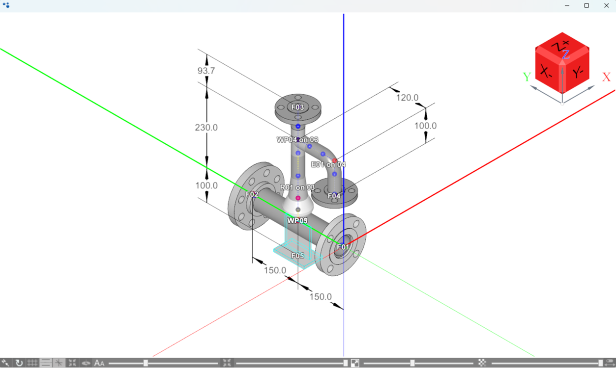 Isometric spool review window

Video guide: Moving the Start Point During a Survey (0:55)
Summary: Useful technique when surveying large spools with restricted line-of-sight.
Orientation Point (OP) for straight spools
An Orientation Point (OP) establishes Top Dead Centre (TDC) for straight pipe spools lacking distinguishing geometric features.
1. Record a single point at the top center of Flange 01, positioned at Top Dead Centre between the upper bolt holes. 2. Proceed with the flange survey as normal. 3. Mark the physical OP location on the spool body to ensure correct site installation orientation.
Video guide: Orientation Point Procedure for Straight Spools (2:56)
Flange and support observations
Video guides:
Step 3: Analysis and Deviation Verification
The analysis module compares captured survey coordinates against design geometry to calculate dimensional deviations.
- Vector error: Coordinate distance (X, Y, Z) between measured work points and design centerlines.
- Alignment error (Touch Point): High-point location on a flange face that will make contact first with a mating flange. The displayed value represents the gap opening (in mm) on the opposite side of the face.
- Rotational error: Angular rotation error of bolt-hole patterns relative to design reference axes.
Interpreting deviation reports


Final report and analysis controls

Video guide: Analysis View Controls and Model Navigation[cite: 1]
Summary: Explains model rotation, vector arrow scaling, toggling point spheres, adjusting font sizes, setting vector tolerance thresholds, and launching PDF previews[cite: 1].

