Automet® FAB - Design Input: Pipe Connections: Difference between revisions
No edit summary |
No edit summary |
||
| Line 6: | Line 6: | ||
<gallery mode = "packed" heights= 250 px> | <gallery mode = "packed" heights= 250 px> | ||
File:KB 55a.png| | File:KB 55a.png|Pipe connection options | ||
</gallery> | </gallery> | ||
Revision as of 10:01, 25 March 2024
Pipe Connections
This video automet® FAB - Design Input - Pipe Connections shows how to enter each of the below pipe connections in automet FAB.
There are numerous types of pipe connections; those available in automet are listed below. The weldolet pipe connection is the default and can be changed by the user as needed.
-
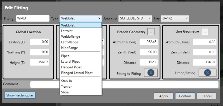 Pipe connection options

Because pipe specifications can change at a connection, the pipe schedule can also be adjusted, and with small diameter connectors, this is fairly common. If you are unsure, use the default, standard schedule (STD).
When creating a fitting to fitting where the schedule is set to match the drawing, the branch length should correspond with the drawing length. To get this, the user can adjust the specification of the branch flange.
Pipe connections can be rolled or offset. The distinction between offset and rolled is that the flange face remains on the grid when offset. When rolled, the flange remains square to the fitting but is not on the grid-line.
Offsets
This is an offset pipe connection. The weldolet is offset 20 mm south of the pipe's centre line. The image shows the rectangular and the polar settings.
-
 20 mm offset weldolet

Rolls
below is a pipe connection with a roll. The weldolet is rolled 20 mm south of the pipe's centre line, which means the connector revolves around the pipe at an angle of 7.55°. The image shows both the rectangular and the polar coordinates. By using the polar/rectangular button, the values can be entered in mm as grid offsets (rectangular) or a bearing and distance (polar). Other pipe connectors, like latrolets and weldoflanges are fittings with lengths established by the database. The exceptions are stab-ins, trunnions and shoes.
-
 Weldolet rolled 20 mm south of the pipe's centre line

Stab-in
A stab-in is a branch connection that does not have a fitting. A pipe saddle profile is used to link the branch pipe to the line pipe. Stab-ins, like all pipe connections, can have offset geometry if required.
-
 Pipe stab in with offset geometry

Trunnion
When creating supports on pipes such as shoes and trunnions, pipe connections (PC) are used. Trunnions are typically installed on fittings. An example of a pipe connection trunnion is shown below. It should be noted that trunnion base plates cannot be oriented.
-
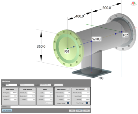 Trunnion

Shoe
A shoe is also defined as a pipe connection (PC), and can be a plate or a box for the support steelwork. Shoe-support base plates can be oriented and their default orientation is along the line of pipe. This can be changed as required. Shoes can be placed at any orientation around a pipe.
-
 Shoe example
-
 Shoe example


-
 Box for steelwork
-
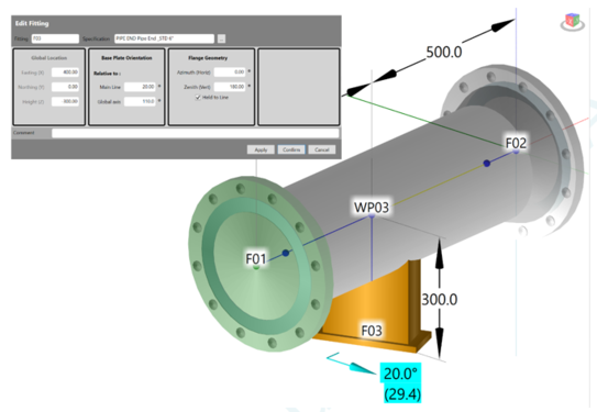 Offset box for steelwork
-
 Shoes at different orientations


