Training Path Module 5: Difference between revisions
| Line 43: | Line 43: | ||
<gallery mode = "packed" heights= 400 px> | <gallery mode = "packed" heights= 400 px> | ||
File:Analysis controls2.png| Controls | File:Analysis controls2.png| Controls | ||
</gallery> | |||
<gallery mode = "packed" heights= 400 px> | |||
File: KB 250b.png| Further controls | File: KB 250b.png| Further controls | ||
</gallery> | </gallery> | ||
| Line 50: | Line 53: | ||
<gallery mode = "packed" heights= 300 px> | <gallery mode = "packed" heights= 300 px> | ||
File: KB 251.png| Tolerance exceeded (example) | File: KB 251.png| Tolerance exceeded (example) | ||
</gallery> | </gallery> | ||
Revision as of 08:46, 22 July 2026
Overview
By selecting Visual Report from the main screen after you have finished a survey, you can see how your measured data compares to the original design data.
The user can then use the tools within the visual report to look at the data in a variety of different ways. The survey data can be rotated and translated, flanges can be fit, unfit or zeroed, and you can also choose how the software prioritises particular data.
This detailed section will try to show you how all of these tools work so you can understand your survey results.
Take your time with the information and try to practice alongside it.
-
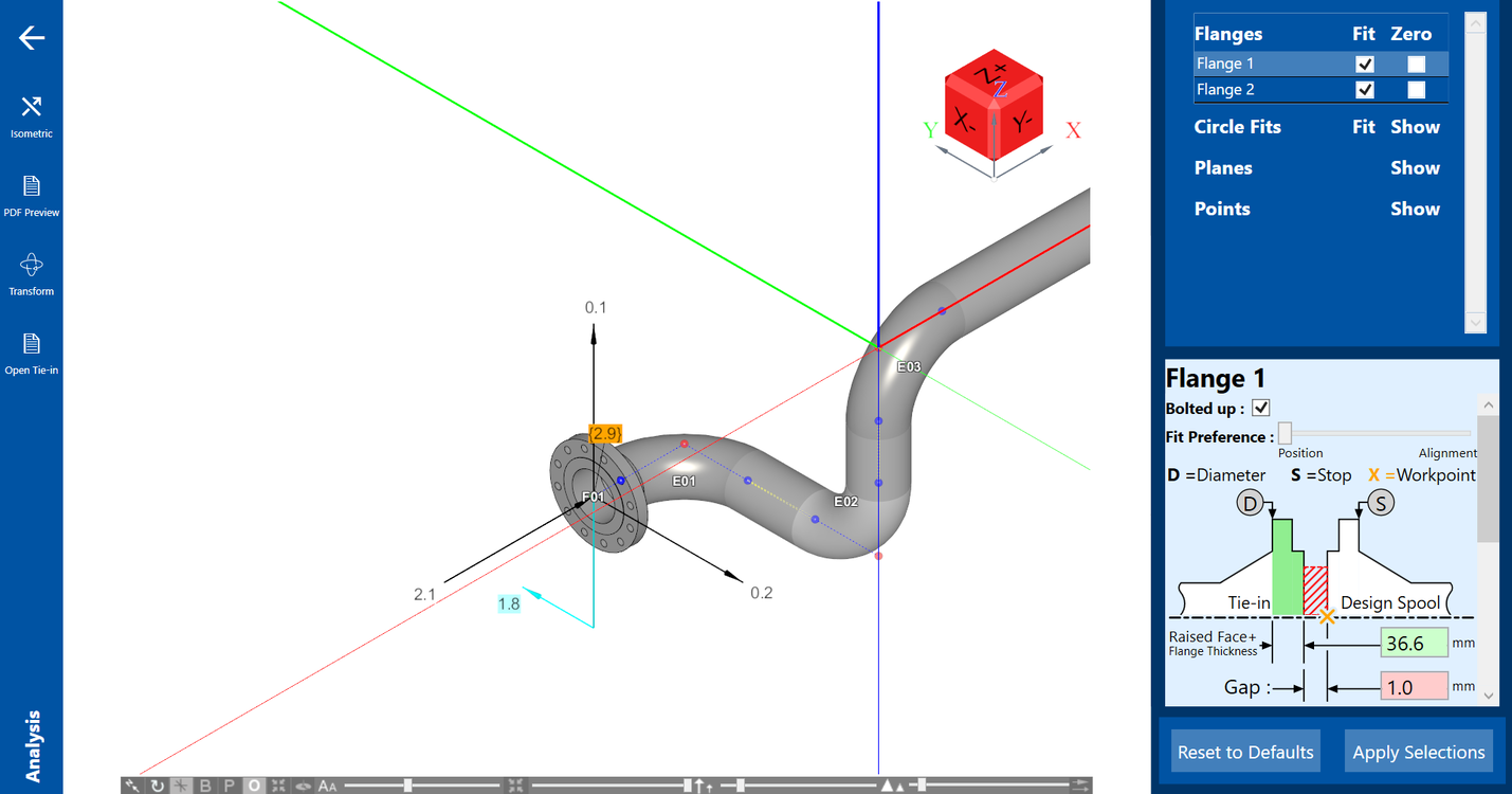 Example survey results

Files
To view a survey within analysis, you will always need two files: survey (.SUR) and design (.DES).
If you want to open a previous survey file, load the SUR file by pressing the Open for Analysis to the right of Survey File: - the design should load automatically.
If you have just completed a survey, the files will already be in place, and you can just click Visual Report.

Drawing Controls
There are a variety of controls within the vector error graphical report. See the images to view a full list of all the available controls.

-
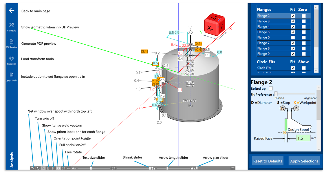 Controls

-
 Further controls

The controls allow you to improve the report layout and clarity. This is the report cleaned up and the tolerance set to 1.5mm. All values above 1.5mm are now shown in red.
-
 Tolerance exceeded (example)

What is shown on the Visual Report
The first and most crucial thing to know is that all values presented are deviations from the design, and if the pipe spool was manufactured exactly as per the design, all values would be zero.
Vector Errors
The black arrows show the measured error in your selected units and in a particular direction (X, Y and Z). The below flange was measured 1.4 mm too high, 0.6 mm too far north and 0.8 mm too far east. Fixing these errors means moving the flange in the opposite direction to the arrows by the stated amount.

Bolt Hole Rotation
The blue arrows show the rotational error in mm and the direction of the error.

Touch Point
The adjoining flange will touch here first where the line from the centre of the flange crosses the outer edge of the raised face (or OD if its a flat face flange) - this is the high point. Move the flange back towards the pipe, by the stated amount to fix the error.

Open Pipe Ends Touch Point
The adjoining pipe will touch where the line crosses the outer edge of the pipe first – this is the long point.

Fit Tools

The default fit of the survey data is defined as the best match between all observational data and the design data. The default fit is always given first, using all available data.
This is an average of all the errors captured during the survey. This means, one large error at a flange can make other flanges look worse.
The user can quickly review other orientations of the survey data by using the tools on the right.
These tools enable the user to manipulate and present data; they are discussed in greater depth later in this section.
Transform
The transform button allows the user to alter survey data with six degrees of freedom. This means that the survey results can be translated and rotated around the X,Y, and Z axes.
Flange Information and Controls

Bolted up
The software algorithm automatically sets the bolted-up condition if it expects (based on survey data) that the flange is bolted up. This is determined by calculating the distance between the diameter-point plane and the stop point.
If the flange is not bolted up, the user can override it.
Diameter - Stop - Workpoint
The circled D (diameter point plane) and S (stop point) indicate the where you took these measurements during your survey.
The tie-In flange and the design spool refer to the pipe spool loaded at the start of the survey.
Gap and flange thicknesses can be updated to tape-measured values; the database defaults are displayed initially.
Ignore length
This option ignores the vector in the direction of length.
When a pipe spool has pipe ends (i.e. open ends of pipe with no flanges), the default is to ignore the length. The length error is not considered and does not affect the best fit. This option allows for pipe over length. If this is not the case, then the pipe over length would affect the report results, so by default, pipe lengths are ignored.
Any flange can be configured to ignore length (if necessary), and any pipe open end can be configured not to ignore length.
Fit preference
The fit preference slider controls the best-fit weighting for each flange/pipe end.
- Position prioritises reducing the vector/positional error (the black arrows).
- Alignment prioritises reducing the the touch point error (gold value) or the alignment of the flange faces.
All surveys deafult to position unless there is a large error, and then the user will have the option to change all flanges to alignment from the outset.
The slider also allows you to balance the preference between the two. You can play with this to see if theres a position you prefer. Just use the Reset to Deafualts button to get back to where you started - your data is never corrupted.
Individual Bolthole Observations
There is a table under the flange which displays each of the bolthole measurements taken.
For your selected flange, you can see the pitch (the angle between the boltholes) and radius (the difference from the database radius) errors for each bolt-hole measurement.
If you see a large error with one of the measurements, you might want to take this out of the calculation, as it could distort the real assessment of PCD etc. Use the Fit checkbox to do this.
When checking pipe ends, the radius errors are diameter points.
Touchpoint at OD
The size of the gap opposite the touchpoint is normally displayed for the location at the flange raised face.
If this option is selected, the size of the gap will be displayed at the flange outside diameter .
Pos/Face error
These are for internal use - they can be ignored.
Arrow/Touchpoint size
The size of the vector error arrow can be changed for an individual flange or pipe end.
Additionally, the length of the touchpoint leader-line can be changed for an individual flange or pipe end
Fit Checkbox
Vector error graphical analysis is used to access and manipulate survey data; it also displays survey information such as flange thicknesses and the types of devices used.
- The fit check box allows you to include spool elements in the fit. Unchecking this box removes that item from the mathematical best-fit analysis, but does not remove the values from the report.
- Show for circle fits reveals or hides the circle fit values on the report.

Zero a Flange
You can isolate a gross error using the fit and zero options within the automet analysis section.
By default, automet will average out the error on all flanges and give you the best-fit option. All surveyed data points have been fitted to the design using a method known as least-squares averaging. Importantly, this method masks gross errors. We can use the option to drop a flange from the fit to show us where gross errors are located.

First, we zero flange one by selecting the zero-option box at flange one. Press the apply selections button to see the change in the visual report.
The zero option does not change the report's orientation - the coordinates are translated; shifted along the grid lines, to match the design co-ordinates at flange one.
You can now see that flange one has zero vector errors.


This pipe-spool report contains some gross errors. You can see this at the touch points on both flanges - there are also large vector errors at flange two.

Dropping a Flange From the Fit
For this example, the zero option at flange one has been unchecked, as it will have no effect on the outcome of the next action. We uncheck the fit at flange two.
We call this 'dropping a flange from the fit'.
Dropping a flange from the fit has a significant impact and the report now looks very different. Only F01's surveyed data points have been fitted to the design.
Because there are only two flanges, flange one can be zero in all aspects, including position, orientation, and alignment. Even though flange two was not included in the fit, its position, orientation, and alignment are still displayed.
Here is a pipe spool with more than two flanges.

Manually Moving the Spool
Align to the Grid
To see how to align parts of the spool to the grid, have a look at this video: Aligning to the grid in analysis transform.
Rotate
You can rotate the spool around its components in the X, Y and Z axes to see how the survey results might look better over the design requirements: Rotate your survey results
Translate
You can also translate (nudge) the whole spool in 6 axis directions (east/west, north/south, up/down) to see how the survey results might look better over the design requirements: Translate your survey results
PDF Preview

Transform

Open Tie-In

Controls for Iso View


.
Reports
Three reports can be generated: Visual, Text and QA.
Text and QA reports are available after setting up the survey data in the visual report interface.
The visual report transforms the survey data and compares it to the design.
The visual report displays vector errors in position, flange alignment (touchpoint) and rotational errors.
This report is the most effective way to observe deviations from the design for pipe spools with multiple configurations.
The spool can be viewed in any orientation, while the text remains flat.