Training Path Module 2
Baseline Design Requirement
automet® FAB requires a design file (`.DES`) to survey against. This baseline enables the system to compare as-built observations directly against nominal design requirements.
There are two methods available for generating design input files.
Method 1 – Importing IDF or PCF Files
Uploading an IDF or PCF file exported from plant design systems (such as PDMS, Smart 3D, or CADWorx) is the fastest way to import spool geometry.
- Automatic model creation: automet® FAB extracts component geometry, nominal dimensions, ratings, and flange specifications to build the `.DES` baseline instantly.
- File organization: Save exported files within project-specific subfolders in the `SURVEY DATA` directory on your `C:\` drive before importing them into automet® FAB.
-
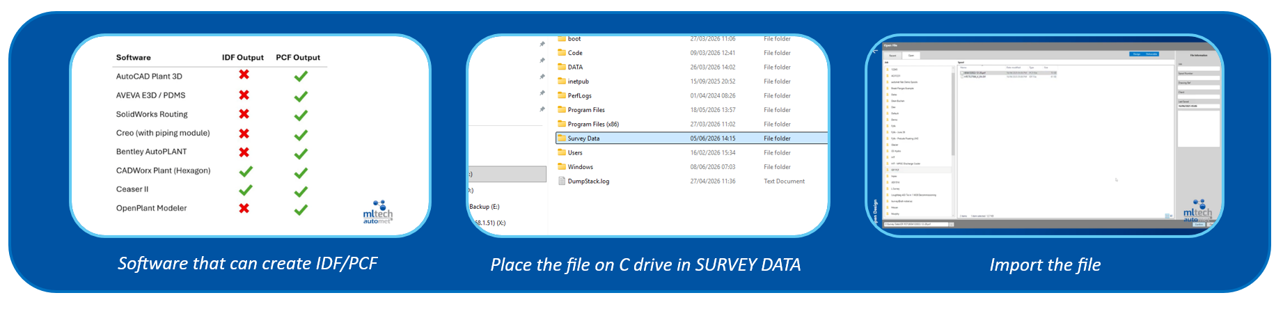 Importing IDF/PCF files to create automet® design models

Video guide: Import IDF/PCF Files into automet®
Summary: Demonstrates selecting and uploading plant design format files (IDF/PCF) into automet® FAB to generate an instant survey-ready `.DES` model.
Method 2 – Manual Design Entry
All operators must master manual design entry. Regardless of CAD file availability, field adjustments, spool edits, and custom component modifications are routinely required during fabrication surveys.
Step-by-step video playlist
Video guide: Configuring a New Design File
Summary: Setting up project metadata, nominal diameters, schedule selection, and global orientation baselines for a new `.DES` file.
Video guide: Setting Up and Changing Flanges
Summary: Defining flange types, pressure classes, face ratings, gasket allowances, and bolt-hole orientations.
Video guide: Inputting and Editing Elbows
Summary: Inputting standard long-radius/short-radius elbows, custom turn angles, and tangent lengths.
Video guide: Inputting and Editing Reducers
Summary: Adding concentric and eccentric reducers, specifying face-to-face lengths and flat-side orientations.
Video guide: Inputting and Editing Pipe Connections
Summary: Defining branch connections, stub-ins, weldolets, and offset branch locations along main headers.
Video guide: Inputting and Editing Tees
Summary: Configuring equal and reducing tees, specifying branch centerline lengths and run orientations.
Video guide: Creating Break Flanges
Summary: Inserting intermediate flanged connections along complex spool assemblies to split models into manageable survey sections.
Video guide: Working Out and Adding Pipe Falls
Summary: Calculating gradient slopes and applying vertical fall angles across sloped pipe runs.
Video guide: Understanding Polar Coordinates
Summary: Inputting compound bends, skew angles, and off-grid vector orientations using polar coordinate entry.
Support for new users
If you encounter unusual isometric configurations or require assistance converting client drawings into automet® design models, contact MLTech support at info@mltech.co.uk. The support team routinely assists new users by building initial design models and providing practical modelling guidance.
Module 2 Self-Check
Before advancing to Module 3, verify that you can perform the following tasks independently:
- Import an IDF or PCF file and verify generated geometry.
- Manually construct a complete pipe spool within Design Input.
- Modify existing flange specifications, schedules, and component geometry.
- Input compound angles and off-grid piping directions using polar coordinates.
Practice by inputting several isometric client drawings into automet® FAB. Set the global coordinate position of Flange 01 (if supplied on the isometric) and verify calculated coordinates for remaining terminal flanges. Ensure gasket thickness allowances are accounted for when comparing calculated work points against drawing dimensions.