Training Path Module 5: Difference between revisions
| Line 307: | Line 307: | ||
</div> | </div> | ||
== Text Report == | |||
Contains tabular alignment, orientation, and global coordinate comparisons essential for field site surveys. | Contains tabular alignment, orientation, and global coordinate comparisons essential for field site surveys. | ||
< | <!-- ===================== MAIN SUMMARY CARD ===================== --> | ||
File:PDF Link Text Report 01.png|Text | <div style="margin:16px 0 20px 0; padding:16px 20px; border:1px solid rgba(128,128,128,0.35); border-top:4px solid #3366cc; border-radius:6px; background:#ffffff; text-align:center;"> | ||
</ | <div style="font-weight:bold; font-size:110%; margin-bottom:8px; color:#3366cc;">Text Report Coordinate Summary Page</div> | ||
[[File:PDF Link Text Report 01.png|center|700px]] | |||
</div> | |||
<!-- ===================== 2 x 3 GRID ===================== --> | |||
<div style="display:flex; flex-wrap:wrap; gap:16px; margin:16px 0 20px 0;"> | |||
<!-- ROW 1 --> | |||
<div style="flex:1 1 30%; min-width:280px; padding:16px 20px; border:1px solid rgba(128,128,128,0.35); border-top:4px solid #3366cc; border-radius:6px; background:#ffffff; text-align:center;"> | |||
<div style="font-weight:bold; margin-bottom:8px; color:#3366cc;">Flange Specification & Gasket Summary</div> | |||
<div style="margin-bottom:10px; text-align:left;">Displays design vs. actual flange angles, bolt-hole rotation, OD/PCD dimensions, and gasket gaps.</div> | |||
[[File:Text Report Flange Info.png|center|280px]] | |||
</div> | |||
<div style="flex:1 1 30%; min-width:280px; padding:16px 20px; border:1px solid rgba(128,128,128,0.35); border-top:4px solid #3366cc; border-radius:6px; background:#ffffff; text-align:center;"> | |||
<div style="font-weight:bold; margin-bottom:8px; color:#3366cc;">Calculated Work Point Centerlines</div> | |||
<div style="margin-bottom:10px; text-align:left;">Shows actual, design, and positional mismatch error coordinates for each flange center point.</div> | |||
[[File:Text Report Centre Locations.png|center|280px]] | |||
</div> | |||
<div style="flex:1 1 30%; min-width:280px; padding:16px 20px; border:1px solid rgba(128,128,128,0.35); border-top:4px solid #3366cc; border-radius:6px; background:#ffffff; text-align:center;"> | |||
<div style="font-weight:bold; margin-bottom:8px; color:#3366cc;">Plane Point Coordinate Locations</div> | |||
<div style="margin-bottom:10px; text-align:left;">Lists 3D coordinates ($X, Y, Z$) for points taken across the flange face using laser or prism.</div> | |||
[[File:Text Report Plane Points.png|center|280px]] | |||
</div> | |||
<!-- ROW 2 --> | |||
<div style="flex:1 1 30%; min-width:280px; padding:16px 20px; border:1px solid rgba(128,128,128,0.35); border-top:4px solid #3366cc; border-radius:6px; background:#ffffff; text-align:center;"> | |||
<div style="font-weight:bold; margin-bottom:8px; color:#3366cc;">Individual Observed Point Coordinates</div> | |||
<div style="margin-bottom:10px; text-align:left;">Displays measurement type (laser or prism) and exact raw coordinate readings.</div> | |||
[[File:Text Report Points.png|center|280px]] | |||
</div> | |||
<div style="flex:1 1 30%; min-width:280px; padding:16px 20px; border:1px solid rgba(128,128,128,0.35); border-top:4px solid #3366cc; border-radius:6px; background:#ffffff; text-align:center;"> | |||
<div style="font-weight:bold; margin-bottom:8px; color:#3366cc;">Flange Midpoint Coordinate Summary</div> | |||
<div style="margin-bottom:10px; text-align:left;">Calculates midpoints and average separation distances across crossover locations between flanges.</div> | |||
[[File:Text Report Mid-Points.png|center|280px]] | |||
</div> | |||
< | <div style="flex:1 1 30%; min-width:280px; padding:16px 20px; border:1px solid rgba(128,128,128,0.35); border-top:4px solid #3366cc; border-radius:6px; background:#ffffff; text-align:center;"> | ||
<div style="font-weight:bold; margin-bottom:8px; color:#3366cc;">D-Point Location Reference States</div> | |||
<div style="margin-bottom:10px; text-align:left;">Visual key showing the 6 possible diameter point placement states (bolted vs. open, front vs. back).</div> | |||
[[File:Text Report 6 States Bolted Design, Bolted Tie-In, Design Front, Design Back, Open Tie-In Front, Open Tie-In Back.png|center|280px]] | |||
</div> | |||
File:Text Report | |||
</ | |||
</div> | |||
</ | |||
=== QA Integrity Report === | === QA Integrity Report === | ||
Revision as of 08:12, 23 October 2026
Overview
Selecting Visual Report from the main application menu following a survey compares captured field observations against design specifications (`.DES`).
The visual analysis suite enables surveyors to rotate and translate models, include or exclude specific flanges from least-squares fit calculations, zero individual tie-ins, adjust fit weighting preferences, and isolate gross fabrication errors.
-
 Graphical visual analysis display comparing survey to design

File Dependencies and Opening Surveys
Analyzing survey data requires two corresponding files:
- Survey File (`.SUR`): Contains observed field coordinate data.
- Design File (`.DES`): Contains baseline CAD model geometry.
To analyze a previously completed survey, select Open for Analysis adjacent to **Survey File:** on the main interface—the corresponding design file loads automatically. If a survey was just completed, click Visual Report directly.
-
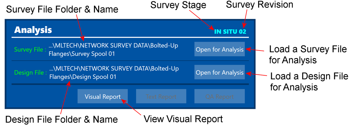 Main menu analysis launch controls

Visual Report Controls
Navigation and Interface Controls
-
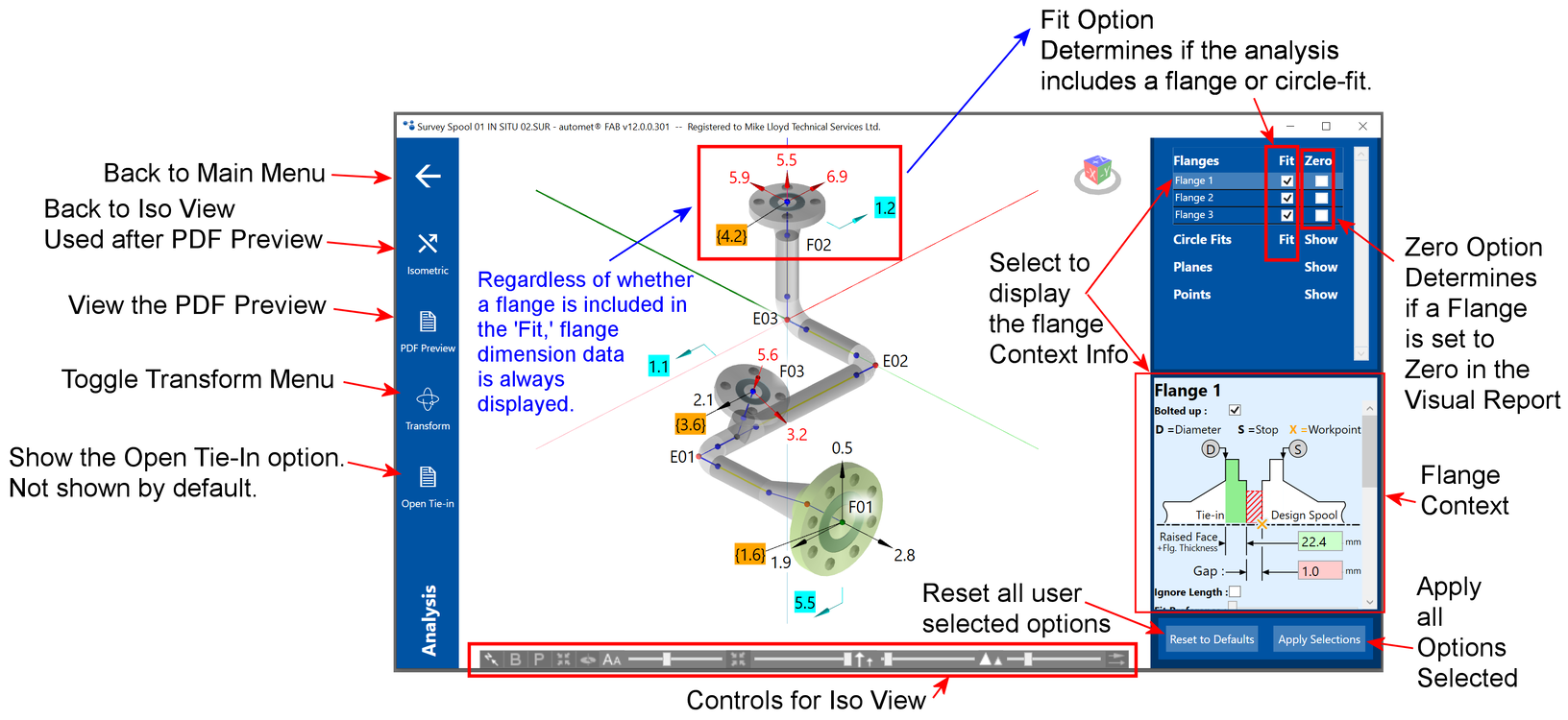 Main visual report button layout

-
 Reset camera view (North to top-left)
-
 Toggle back vectors on/off
-
 Toggle observed points spheres on/off
-
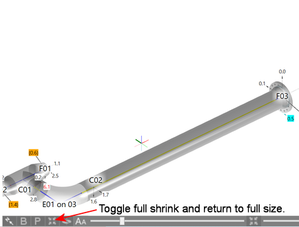 Toggle model full shrink
-
 Toggle model full size
-
 Toggle free rotate vs. turntable mode
-
 Expanded viewer controls and display scaling sliders
Video guide: Controls for Iso View in Analysis (2:41)
Summary: Demonstrates camera rotation, wheel zoom, mouse pan, camera resets, showing observed point spheres, scaling vector arrows, and adjusting model shrink parameters.
- North Arrow: Resets camera orientation so North points top-left.
- B Button: Toggles display of back vectors on/off.
- P Button: Toggles observed data point spheres on/off.
- Shrink Buttons: Toggle full model shrink or restore to full size.
- Free Rotate: Switch between free-orbit rotation and turntable mode.
-
 North view reset
-
 Toggle back vectors
-
 Toggle point spheres
-
 Full shrink
-
 Full size
-
 Turntable / Free rotate
- Vector Scaling: Adjust size and arrowhead dimensions for vector arrows.
- Font & Label Scaling: Customize text dimensions across the model.
- Point & Opacity Controls: Adjust sphere sizes, leader lengths, and transparency.
-
 Expanded viewer controls and display scaling sliders
Video guide: Controls for Iso View in Analysis (2:41)
Summary: Demonstrates camera rotation, wheel zoom, mouse pan, camera resets, showing observed point spheres, scaling vector arrows, and adjusting model shrink parameters.
- Resets camera orientation so North points to the top-left.
-
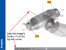 North view reset
- Toggles display of back vector error arrows on and off.
-
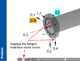 Toggle back vectors
- Toggles observed survey data point spheres on and off.
-
 Toggle point spheres
- Fully shrinks component lengths to highlight flange orientations.
-
 Full shrink view
- Restores pipe spool model to full proportional length.
-
 Full size view
- Switches between free 3D orbit rotation and turntable mode.
-
 Free rotate / turntable
- Sliders: Adjust font dimensions, shrink ratios, vector arrow scaling, arrowhead sizes, opacity, and positional tolerance thresholds.
-
Expanded viewer controls and display scaling sliders
Video guide: Controls for Iso View in Analysis (2:41)
Summary: Demonstrates camera rotation, wheel zoom, mouse pan, camera resets, showing observed point spheres, scaling vector arrows, and adjusting model shrink parameters.
Manual Transforms and Model Adjustments


Open Tie-In Surveys
When analyzing open tie-in site surveys, enable the **Open Tie-In** function to prevent coordinate fit distortions.
-
 Open tie-in analysis control panel

Report Generation
automet® FAB generates three specialized documentation reports following analysis setup:
Visual Error Report
3D graphical view displaying vector arrows, rotational offsets, and face touch-point gap dimensions.
Text Report
Tabular coordinate listing showing actual vs. design coordinates, D-point locations, and alignment angles.
QA Integrity Report
Quality audit verifying face planarity, PCD errors, device types, and multi-setup instrument move precision.
Visual Error Graphical Report
All displayed values represent deviations from design; a perfectly manufactured spool yields all zero values.


Text Report
Contains tabular alignment, orientation, and global coordinate comparisons essential for field site surveys.


QA Integrity Report
Validates observation quality, face flatness (plane error), target seating (Max OD error), and instrument setup resection accuracy across multiple station moves.
-
 QA integrity report page 1
-
 QA integrity report page 2 (support plates and instrument moves)


-
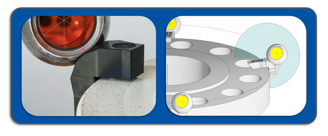 Plane error warning (face planarity > 2 mm)
-
 Max OD circle error (unseated target device)
-
 Pitch Circle Diameter (PCD) error diagram
-
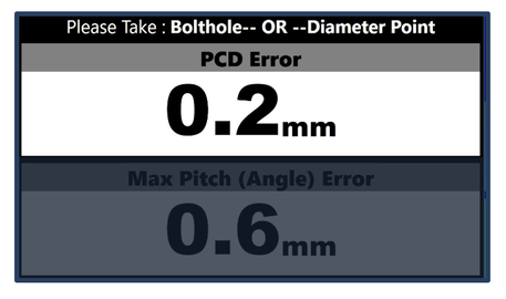 PCD deviation readout
-
 Max bolt-hole pitch error diagram
-
 Max pitch angle deviation readout


Live QA Report During Capture
QA integrity reports can also be reviewed live during survey capture via the **Objects Tab**, allowing operators to identify and re-shoot flawed points before disturbing total station setups.
-
 Live capture QA report view 1
-
 Live capture QA report view 2


PDF Export Preview
To generate customer-facing PDF documentation, align the 3D model on screen to present all relevant callouts clearly, then click **PDF Preview**.
-
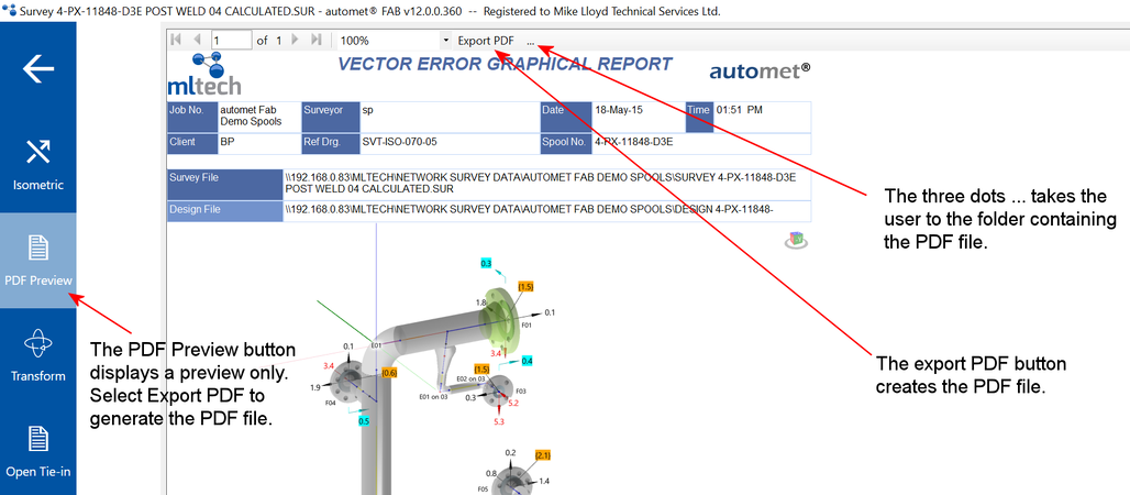 PDF export preview window

Training Path Completion & Next Steps
Congratulations on completing the **automet® FAB Self-Guided Learning Path**.
To continue expanding your technical expertise, explore the following specialized workflows:
- Automet® FAB - Site Survey – Detailed field site survey procedures.
- Automet® FAB - Control Capture Methods – Advanced resection networks and control station management.
- Pressure Vessels – Modelling and surveying pressure vessel nozzles and shell alignments.
For technical assistance or training inquiries, contact MLTech support at **info@mltech.co.uk**.