Training Path Module 5
Overview
Selecting Visual Report from the main application menu following a survey compares captured field observations against design specifications (`.DES`).
The visual analysis suite enables surveyors to rotate and translate models, include or exclude specific flanges from least-squares fit calculations, zero individual tie-ins, adjust fit weighting preferences, and isolate gross fabrication errors.
-
 Graphical visual analysis display comparing survey to design

File Dependencies and Opening Surveys
Analyzing survey data requires two corresponding files:
- Survey File (`.SUR`): Contains observed field coordinate data.
- Design File (`.DES`): Contains baseline CAD model geometry.
To analyze a previously completed survey, select Open for Analysis adjacent to **Survey File:** on the main interface—the corresponding design file loads automatically. If a survey was just completed, click Visual Report directly.
-
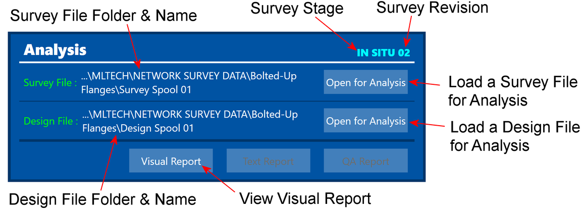 Main menu analysis launch controls

Visual Report Controls
Navigation and Interface Controls


Video guide: Controls for Iso View in Analysis (2:41)
Summary: Demonstrates camera rotation, wheel zoom, mouse pan, camera resets, showing observed point spheres, scaling vector arrows, and adjusting model shrink parameters.
Manual Transforms and Model Adjustments
Open Tie-In Surveys
When analyzing open tie-in site surveys, enable the **Open Tie-In** function to prevent coordinate fit distortions.
-
 Open tie-in analysis control panel

Report Generation
automet® FAB generates three specialized documentation reports following analysis setup:
Visual Error Report
3D graphical view displaying vector arrows, rotational offsets, and face touch-point gap dimensions.
Text Report
Tabular coordinate listing showing actual vs. design coordinates, D-point locations, and alignment angles.
QA Integrity Report
Quality audit verifying face planarity, PCD errors, device types, and multi-setup instrument move precision.
Visual Error Graphical Report
All displayed values represent deviations from design; a perfectly manufactured spool yields all zero values.


Text Report
Contains tabular alignment, orientation, and global coordinate comparisons essential for field site surveys.


Training Path Completion & Next Steps
Congratulations on completing the **automet® FAB Self-Guided Learning Path**.
To continue expanding your technical expertise, explore the following specialized workflows:
- Automet® FAB - Site Survey – Detailed field site survey procedures.
- Automet® FAB - Control Capture Methods – Advanced resection networks and control station management.
- Pressure Vessels – Modelling and surveying pressure vessel nozzles and shell alignments.
For technical assistance or training inquiries, contact MLTech support at **info@mltech.co.uk**.